Super Nintendo (Snes) Recap
Recapping a UK PAL Snes
This was a very easy console to recap for a couple of reasons, I would rank this second only to the C64 for ease of recapping.
Firstly the capacitors seems to be well-fitted first time round; usually with the other consoles the SMDs had one pad which was easily accessible and another which was barely reachable, and secondly because the capacitors were still in great condition even after all this time so there was plenty of good solder to work with to remove them. A few were close together which made them a little more finickety but nothing that really caused any annoyance in the slightest. Also, unlike its predecessor the NES, there’s no awkward RF box welded onto the mainboard itself.
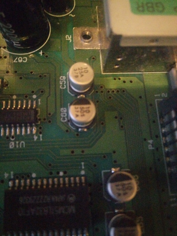
For the UK version of the mainboard there were two versions (Which are printed on the board itself), the main difference as I’ll point out later is that one capacitor (C59) changes from polarised to bi-directional.
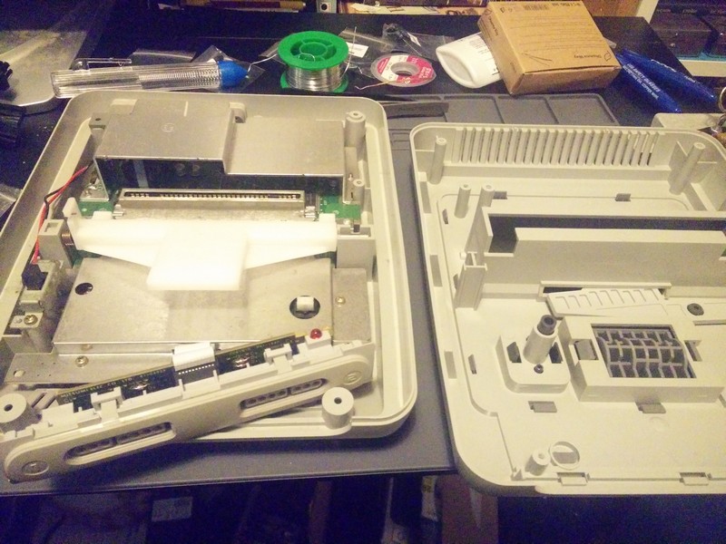
So let’s open it up. To do this You’ll need a special gamebit screwdriver head, but they’re cheap and easy to find on ebay or something.
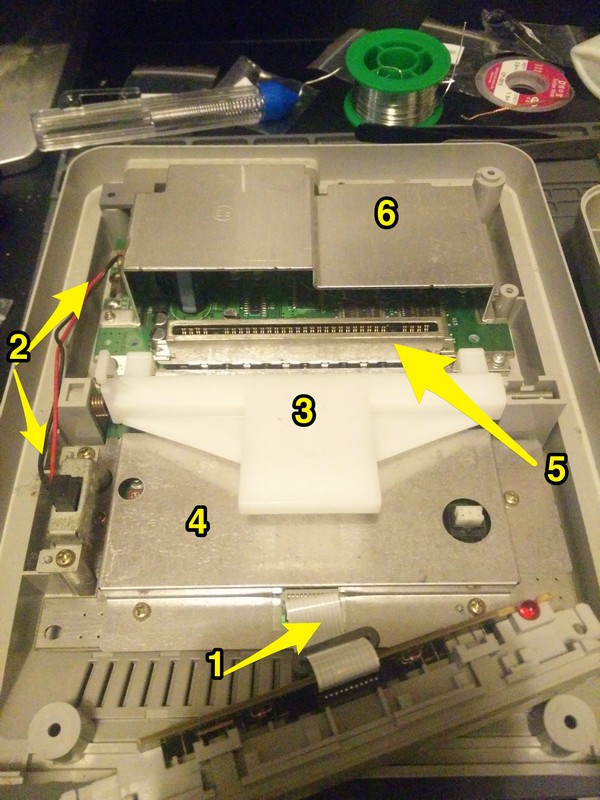
As you can see there are a few leads and controls to remove first then beneath them there are a few layers so it’s best to have a look around and see how they interact with each other. I had success removing them in the order below:
The ribbon cable (1) is remarkably easy to remove and later reseat. After removing the cartridge ejector mechanism (3) it looks at first glance like (4) and (5) are one single piece, but 4 just slots into the top of the cartridge holder (5).
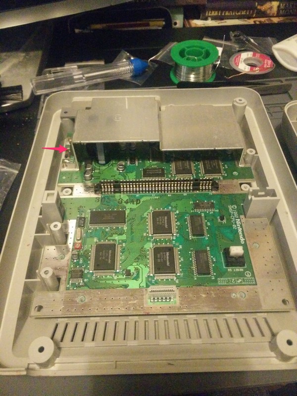
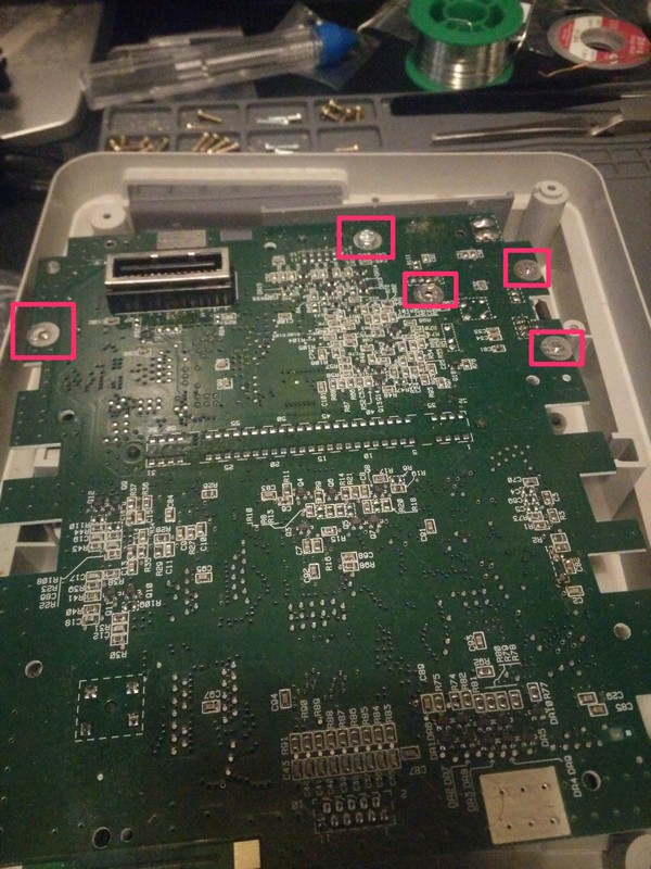
The last shield seen above has a few little gotchas. First there’s a component soldered to the board then screwed into the side of the metal plate (As shown by the arrow), so unscrew this first. Finally, this metal plate is screwed into the PCB from below rather than above, so flip the board over and remove these screws:
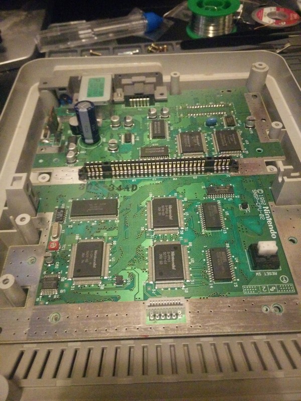
And now we get a full view of our mainboard. One thing I did notice is that the entire inside of these consoles tend to accumulate an incredible amount of dust! before putting everything back together after this process I ended up brushing and wiping both sides of the PCB, the cartridge contacts and the inside of the case, all the Q-tips (fully bio-degradeable if you please!) and cloths came away black.
I didn’t attempt to remove the AV ports at the back, but I’d check next time if I can, just to make removing the capacitors next to it a little easier, but it’s fine either way.
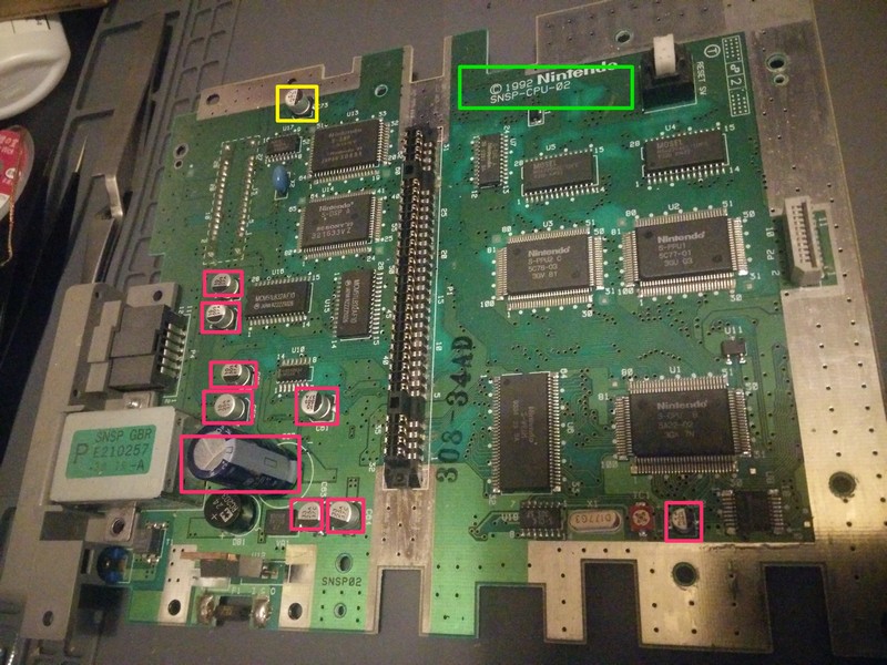
So let’s take a closer look at what we’ll be working with:
The serial highlighted in green is the board number, mine is revision 2 as above, showing that C59 is already bi-directional. The caps in pink are what we’ll be replacing, I left out the one marked in yellow because I didn’t have a replacement cap for that, but it looks in great condition like the rest anyway so it’s not urgent.
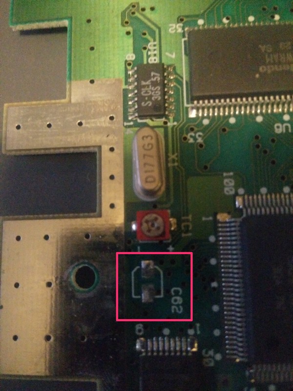
The cap at the bottom right is what I’ll focus on to show how I’ll be doing this, since unlike my previous recap posts what I’ll be doing here is replacing SMD (surface-mounted) caps with through-hole radial caps by just soldering them straight onto the pads.
The black markings on the SMDs show the negative polarity, but if you forget what this was, just align the negative leg of the radial to the flat section of the silkscreen silhouette:
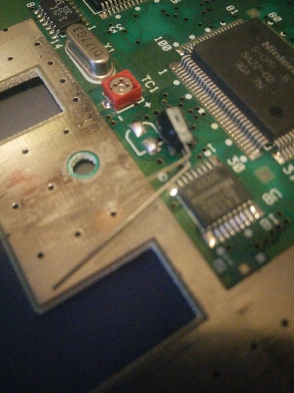
What I then do is use desoldering braid to remove existing solder from the pads, clean it with isopropyl alcohol, apply fresh solder, bend the legs of the cap near the base as shown below:
Then we cut the leg short and press each new “foot” onto the new solder as we apply the soldering iron so the solder melts and the foot sinks in.
The only small difference is the aforementioned C59 as we see below, which unlike the capacitor next to it has no black mark to show polarity as it’s bi-directional. With the first revision board you’d have to remember to ignore the existing polarity but with the second revision it’s easy to spot:
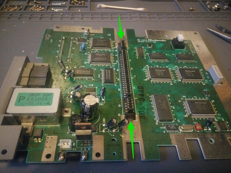
We can see below now how it looks with radial caps standing where the surface-mounted caps were. Where the green arrows are is where the ejection mechanism spans, so I just adjusted the tilt on the capacitor that leans across this area and it was fine:
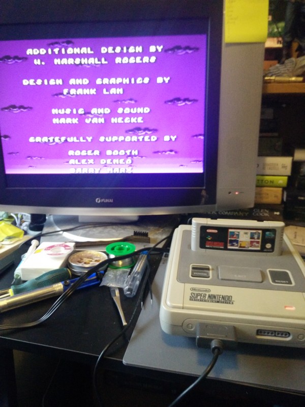
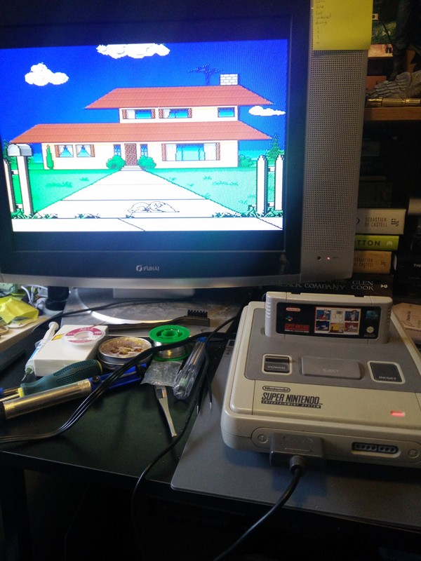
And now we can see the console working, the light and dark colours looking great:
The only other addition I made to this console was a bluetooth controller from 8bitdo: https://www.8bitdo.com/retro-receiver-snes/ This allows me to play the Snes without getting square eyes sat up close to the living room TV, the past couple of decades have just spoiled me with wireless controllers, I found they do the same for the NES so I’ll be getting that too!

