CD32 Recap
Replacing capacitors on a console with famous factory install issues
The next console up for a recap is the CD32. It was pushed up my list because like the Game Gear, it’s a little more notorious for having capacitor-related issues, some of which happened before the console even left the factory.
This was going to be far more complicated and dangerous to my previous recap projects because:
1- CD32s have really shot up in price. You’re looking currently at £300 or so for one and not much less than that for just the mainboard. Even the 3rd party controllers are wildly expensive let alone the 2 originals we have. Unlike the PS5 or something which can at least come down in price, this console is only getting harder to obtain.
2- This is one of my wife’s consoles. So if I mess it up and have to sneakily replace it, it’s going to cost a bomb (See point (1) above)
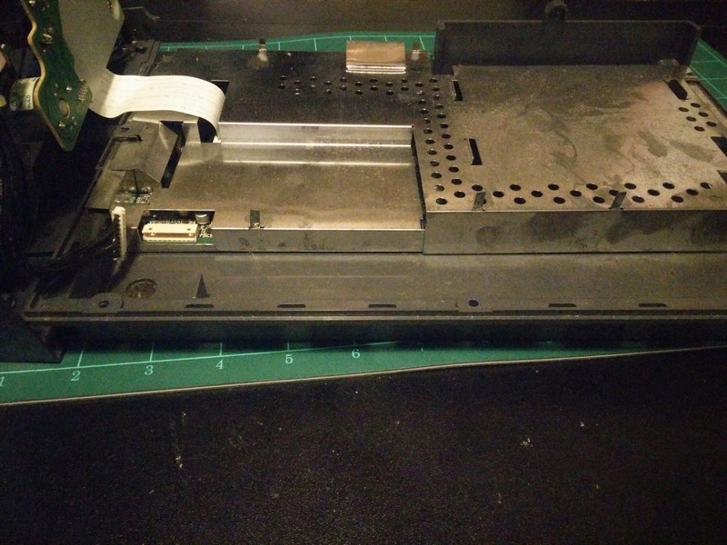
So here we begin opening it up, the mainboard is encased within a metal box which then sits below the CD player in the lower part of the casing.
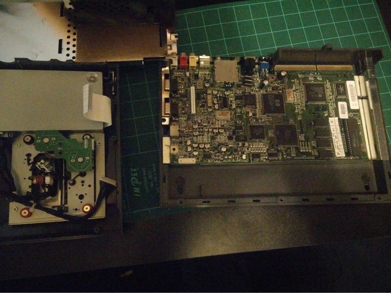
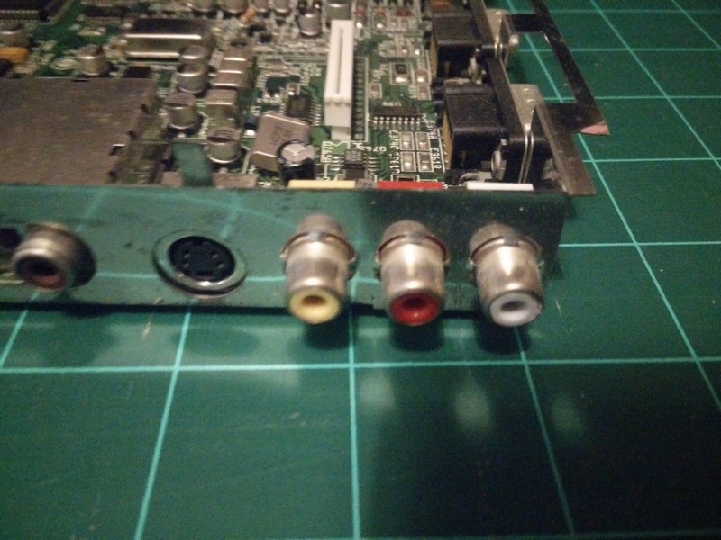
So here after disconnecting the Control ribbon and CD ribbon, we can remove the top part of the case after unbending a few metal tabs, and we can see the upper part of the mainboard. To separate this from the lower half we need to extract the RCA ports from some tabs which are grabbing them and holding them in place:
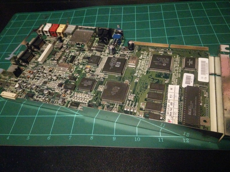
So now we can see what a big job we have waiting for us:
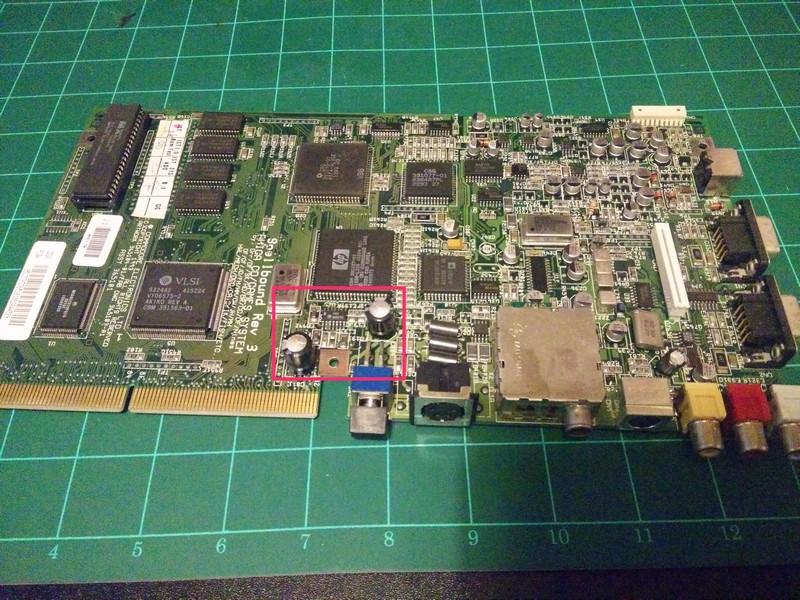
Let’s focus first on the area highlighted in pink, as this is the most obvious problem we’re going to face as it was a manufacturing flaw:
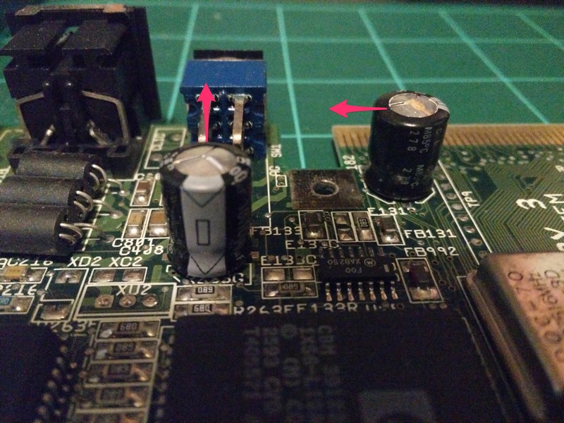
The blue sides of the capacitors show where the negative terminal is, the red arrow shows where it should be, so as we can see both of these are installed incorrectly with the polarity incorrect. Now focus on the top of the capacitors themselves, the metal roof of these should be flat and clean, instead we can see that they bulge and there are visible signs of leakage.
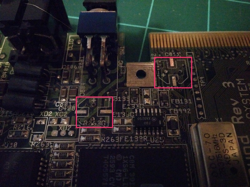
When we remove them we can see in the image above that even the guides on the mainboard were incorrect. The guides clearly indicate which terminal should be used for positive (As shown by the + symbol) and which for negative, so this is why so many of these boards share the same issue. We’re going to ignore these guides and install correctly, the “wrong” way round!
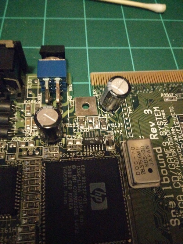
See how both blue negative markers now face in the direction of the power switch.
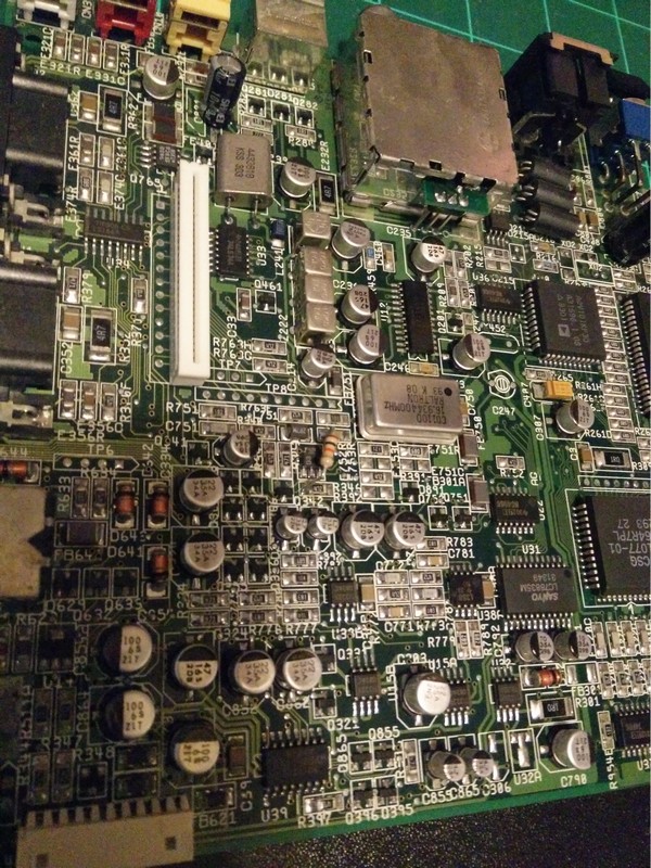
Now what’s next? Well all the rest of the capacitors reside on the left side of the board so let’s look closer at that general area:
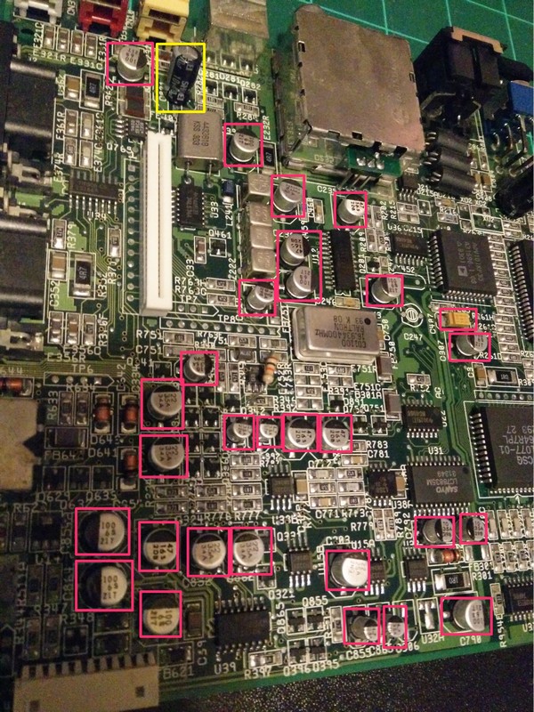
Looks crowded. But which are the bits we’re actually going to replace?
Oh no!
Well at least there’s one more through-hole capacitor (Highlighted in yellow) so that should be easy enough right? Well no, because the electrolyte had essentially formed some sort of concrete in the hole and it took over an hour to clear it sufficiently to insert the replacement. At one point I watched in slow motion as a needle went almost a centimetre deep into my fingertip it was a really fun time.
The SMDs were in varying states of decay. Some were easy to unseat and replace and some were very reluctant to leave their pad be so I had to very gently separate a few pads from their capacitors which were already lifting them slightly off the PCB. There are just so many of them it’s very time-consuming. I ended up doing half on one night then the other half the next day, this time wearing a beautiful plaster on my finger (This actual engineer work is too dangerous I’m going to stick to software “engineering”).
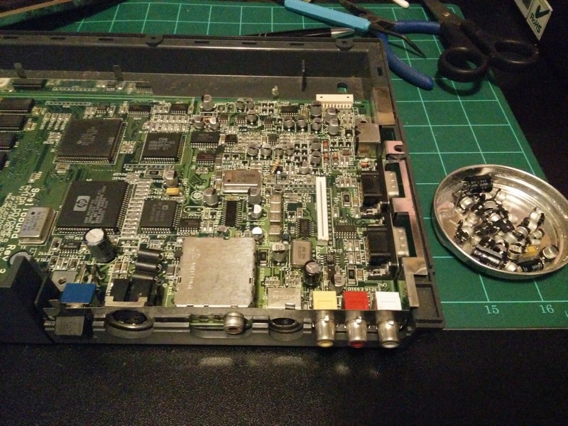
But finally, after hours of arduous work which is both tedious and stressful all at once, here’s what we’re left with, a lovely pile of old discarded caps and their replacements on the mainboard:
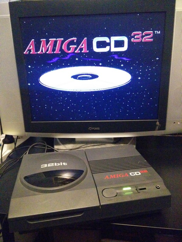
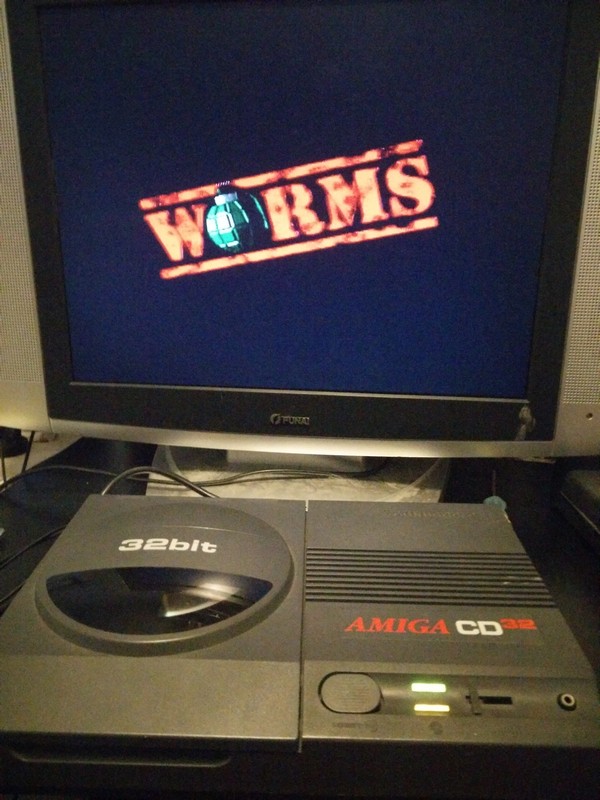
And then put it back together and power it on (Ignore the brightness of the screen, my phone can’t handle taking pictures of displays in the dark):
“Funnily” The CD reader wasn’t attempting to even spin the disc up after the recap, but it turned out the ribbon to the mainboard just needs to be seated very deeply, so pulling it down further with some needle-nosed pliers solved it:

